 626-575-7806
 sales@mag-tran.com
 2108 Seaman Avenue, South El Monte, CA 91733
Below are examples of some of the different models we have built for customers:
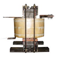 MT-3848
0.338mH end to end
2x 1466Arms
850VDC, 4kVrms Dielectric withstanding
NEMA1 enclosure
MT-3848
0.338mH end to end
2x 1466Arms
850VDC, 4kVrms Dielectric withstanding
NEMA1 enclosure
Our goal is to give our customers the most flexibility possible so they can design and implement our Interphase Transformers into their specific systems. Doing this accomplishes two things:
If for any reason you are having trouble determining the specifications of your next transformer, feel free to give us a call or send us an email. Our sales representatives and engineering staff can help you find the needed information.
| Voltage | Up to 1,500VDC |
|---|---|
| Rated current | Up to 6,500ADC |
| Current imbalance | Up to 6% |
| Expected audible noise | Interphase transformers are inherently noisy, but we have developed construction techniques that help to minimize audible noise. |
| Other Options |
Noise specifications Connection location specifications |
The Interphase Transformer is used “to absorb the difference between the direct voltages of the individual systems and must be designed for the times integral of this voltage” (Schaefer, 1965).
Interphase transformers are used in systems that have two rectifier systems being used in parallel. The need for the Interphase Transformer is present because when connecting rectifiers in parallel, their direct voltages fluctuate. Furthermore, rectifier systems can only be connected in parallel if their fluctuating voltages are equal at any instant. Essentially, their average values must equal and the ripple voltages must coincide. “Under this condition rectifier installations for very high current ratings are sometimes built of several simultaneously commutating and directly paralleled groups” (Schaefer, 1965). In practice, this setup is rarely found.
It is most commonly desired, instead, to displace the ripple voltages so that the combination results in a system with a higher pulse number. “The parallel connection must then be made in such a manner that it does not affect the operation of the individual groups. This is accomplished with an Interphase Transformer” (Schaefer, 1965).
Schaefer, J. (1965). Interphase Transformer Connections. In J. Schaefer, Rectifier Circuits: Theory and Design (p. 31). New York, New York, United States of America: John Wiley & Sons, Inc. Retrieved March 27, 2014